Handling Hierarchy and Repeating Schematic Blocks in gEDA
Schematics often have blocks that get repeated several times. Here I describe how I deal with this situation in gschem with schematics, symbols, and a small script. You can view the script's source code here. You can download the source code from the table of attachments below. Table of ContentsBlocks
To simplify things, consider a circuit board that has several blue LEDs with matching current limiting resistors.Manual Copying and Updating
One way to handle this in gschem is to place, connect, and configure the first resistor and LED, and then manually copy this block each time you need another. While this is simple enough, it has the disadvantage that any change you make to one block has to be manually incorporated into the others. For example, if you change your mind on the current limiting resistor value, you have to find all the current limiting resistors and update them individually. As you load up these basic components with details like footprints, catalog numbers, prices, etc., updating a repeated block can become even more tedious.Hierarchy and Block Instantiation
Here is a summary of what I do in these cases instead:- Create a separate schematic file representing a single block, using special
refdesnames for the block's I/O. - Create a symbol to represent the block, using special
pinlabelnames for the block's pins. - Use the
block-net-rename.scmscript to instantiate any number of blocks. - Insert the instantiated blocks as needed in my schematic.
Block Schematic
In a separate schematic file, place and configure the components of the block. Include input and output symbols from the gschem component library to represent the inputs and outputs for the block. Here is an example schematic for a blue LED, saved in a file calledled-blue-block.sch:
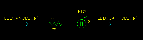
refdes for the input and output are labeled LED_ANODE_{n} and LED_CATHODE_{n}. Later, a script will substitute a block number for the "{n}" when instantiating this block schematic.
Block Symbol
In a separate symbol file, draw a graphical representation of the block. Here is an example symbol for the blue LED block, saved in a file calledled-blue-block.sym:
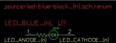
pinlabel values for the pins temporarily visible for the screen shot. They match the corresponding refdes of the block schematic: LED_ANODE_{n} and LED_CATHODE_{n}. Again, the script will substitute a block number for the "{n}" when instantiating this block symbol.
The attribute labeled LED_BLUE_{n} is named block-rename to tell the script to substitute the "{n}" here as well. It is there to identify the block when the instantiated symbol is included in the schematic.
I've made the source attribute temporarily visible, too. Again, the script will substitute the "{n}" with a block number. In my workflow (using yar) the final, renumbered schematic files end with the extension .renum, so this source line will ultimately link an instantiated symbol to its corresponding instantiated schematic. It is important to get the source attribute right because this is how gsch2pcb follows the hierarchy to pick up the block schematics. It is also what gschem uses to implement the "Hierarchy/Down Schematic" command.
Instantiation Script
The block schematic and symbol created above are not used in your schematic directly. Instead, they act as templates for theblock-net-rename.scm script so it can instantiate as many blocks as you need in your schematic. For example, if you need three blue LEDs in your design, you could instantiate them like so:
  $ ./block-net-rename.scm -n 1 -o led-blue-block_1.sch led-blue-block.sch
  $ ./block-net-rename.scm -n 1 -o led-blue-block_1.sym led-blue-block.sym

  $ ./block-net-rename.scm -n 2 -o led-blue-block_2.sch led-blue-block.sch
  $ ./block-net-rename.scm -n 2 -o led-blue-block_2.sym led-blue-block.sym

  $ ./block-net-rename.scm -n 3 -o led-blue-block_3.sch led-blue-block.sch
  $ ./block-net-rename.scm -n 3 -o led-blue-block_3.sym led-blue-block.sym
At this point, the script will have created three new schematic files, and three new symbol files named as specified by the
-o command line option.
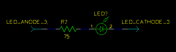
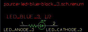
For example, here is what the instantiated schematic for block 3, led-blue-block_3.sch, looks like:
led-blue-block_3.sym, looks like:
Using Instantiated Blocks
Finally, just insert the instantiated blocks as needed into your schematic. Here is an example fragment of a schematic using the instantiated blocks: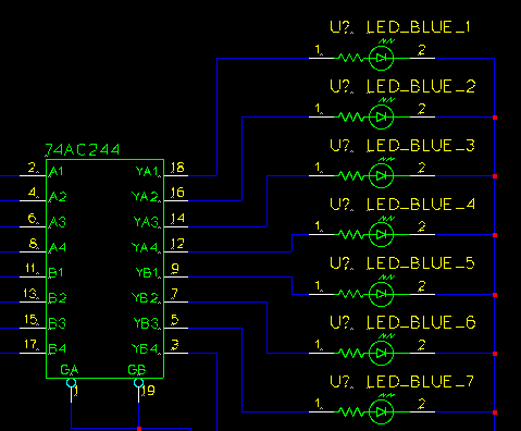
Updating Blocks
To update a block, just modify the base block schematic or symbol files, and rerun theblock-net-rename.scm script on them. This will re-instantiate the blocks with the modified information.
I don't run the instantiation script manually as described above. Instead I use Make to do this automatically whenever an underlying block schematic or symbol has been modified.
| Attachment | Size | Date | Comment | |
|---|---|---|---|---|
| | octw-guile-geda-scripts-1.0.tar.gz | 16.9 K | 11 Sep 2008 - 04:57 | gEDA Guile Scripts 1.0 |
